I am writing this up in case anyone else is dumb enough to try it, and you want to know basically how to do it right.
The
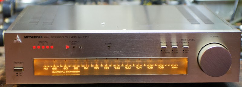
Mitsubishi M-F01 FM Tuner I got the other day had some burnt out bulbs,
turned out 1 white bulb, and both green bulbs were out.
I made the HUGE mistake of removing all the screws on the faceplate to get to the bulbs.
HOWEVER!
I did manage to get the bulbs replaced. I found that the old
incandescent bulbs ran off of 9vdc and that they were all white bulbs
with colored rubber covers, one bluish, and the other Green. The white
light comes from the blue colored one and the green you can figure out
yourself.
It is not necessary to remove the dial knob to remove the faceplate, it is not necessary to remove the faceplate (but I did)
When you remove the faceplate, the dial, and tuning knob fall out. Then the dial string unravels YAY!
In
reality the only thing you have to do is remove the 2 screws that hold
the circuit board in the picture below circled in red. Then carefully
move the circuit board out of the way.
ANYWAYS... I don't have the bulbs and did not want to go on a quest to find some, plus I am impatient. But I did have these:
http://www.modeltrainsoftware.com/ledlights1.html
The
LED's work on a wide range of voltages and it does not matter what
polarity or if you have AC or DC. Being standard LED's they were also
the same size as the old bulbs. The old bulbs were mounted on small
circuit boards, three wires; blue, green, and Black. Blue for the white
light, green for green light and black was ground.
I removed the
little circuit boards and I connected 1 wire from the white LED to the
Blue wire, one wire of the Red LED (I chose Red instead of Green) to the
green wire, and then the remaining wires from both to the black. I used
shrink tube as needed. I installed the bulbs in the dial with hot glue
after verifying that they worked. I did this for both sides (there are 2
sets of lights).
I got it back together and restrung the dial.
Not on station!
On Station!
The only disadvantage to these LED's is that if you connect them to AC
or unfiltered DC they may flicker juuuuuuuust on the edge of your
perception.
I did not take any other pictures because I was too irritated and did not think I was going to get it back together.
11/13/2013
10/29/2013
Refreshing The Fisher XP-9C Speakers Part II
After I received the non polarized electrolytics I replaced them on the crossover. I had to order extra 50uf capacitors as Parts Express did not carry 25uf caps. I put 2 - 50uf caps in series to get 25uf.
To make a good seal around the speakers I picked up some weather stripping. I wanted a good seal since this is an acoustic suspension system.
I used a hair dryer and a vacuum to pop out the pushed in "fried egg" tweeter. One will not pop out and I will have to work on it.
I put everything together and hooked it up to my tube amps. It sound really nice.
10/26/2013
Pioneer SX-434
Found at Goodwill last night. Pioneer SX-434 Stereo Receiver. She
needed a little TLC. I installed 3 new lamps, and a new stereo indicator
light. The old one was in it's correct bracket, but the previous,
previous light base was also in there. I removed that and installed a
new sub mini light, installed the bracket (after removing the mess of
tape on it), and hot glued it in place. Cleaning the pots was a chore as
I had to remove the base, and a circuit board to get to them. Then the
knobs and faceplate were cleaned, and some furniture polish cleaned up
the top.
For a small 15 watt per channel stereo this one has a real wood cover. She sounds pretty decent.
10/21/2013
Merrell SA-30, National Kits STA-24, Radio Shack R90LX066
After years of miserly waiting, I have acquired my first tube integrated
amp from ebay, (Since the one who shall remain nameless) threw away my
"The Fisher 400" Receiver while I was at college in the 80's. This one
arrived Friday 10-19-2013
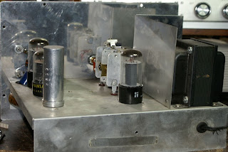
It was listed as an "unknown amp" I did some sleuthing and found that it was either a Radio shack, National Radio, or a Merrell kit amp.
We'll call it a Merrell SA-30 for now.
Auction pics
Things I found wrong with it. There is a large 25 watt? 200ohm resistor that (whoever wired it originally) had used WAY too thin wire. The wire was scorched on either side of the resistor. I replaced it with some larger wire. There is a fluttering/static noise when the selector is on Lo Phone/Tape. The Lo Phono connection has more gain than the other inputs. This means it works real well for my Mp3 player. I can drop the volume on the player down to 50% when hooked up there.
In the picture above of the back of the amp, there are 4 connections for each speaker. I determined that the far right connection is common, the other connections are from left to right. 4ohm, 8ohm, 16ohm. I input a sign wave in to the unit and noted that the amplitude of the wave increased as I went from right to left. The 2 RCA connections below the left speaker connectors. They are not Left and Right Tape out.
The unit supposedly does NARTB equalizing on the phono inputs (I cannot tell).
After about 2 hours listening the Power transformer gets to be about 140°f.
I need to:
get matched tubes for it, though it plays pretty good with the hodge podge that I have in it.
make a cage/cover for it, it had one at some point and there are screw holes for one.
Make a wood base for it.
Properly label everything on the back and remove all the marking pen marks on it.
The filament voltage for the 5U4 on this this amp was over 7 volts A/C, it should be 5. I did some research and calculations that to drop 7.16 volts to 5 volts at 3 amps would take about .76 ohms 6.5 watts. I knew from past experience that it would probably not be that exact a resistor. Most calculators I found said it would take a 1 ohm 6.5 watt resistor.
I picked up 2 - 1 ohm 10 watt resistors. I found that 1 - 1 ohm resistor dropped the voltage down to about 3.5 volts. I tested the 2 resistors in parallel for .5 ohms. That brought the voltage down to 5.07 volts They do get pretty hot.
For now they are mounted sub chassis on a standoff in free air.
For anyone that is interested here is the Schematic.
Right click and open in a new tab or window. Then save the jpg. The notations on the drawing are not mine. The Filter Capacitors are not marked on the schematic and I do not know the correct values. However my amp had 40uf 350v and 20uf 350v multi section caps installed. I would replace them on both channels with 40uf 450v electrolytic caps. There is also a 200 ohm 25watt resistor coming off of the 5u4 pin 8, and before the first filter cap. I am thinking that someone put that in there to limit the voltage because without it the screen grid voltages on the 6V6 tubes is 32 volts to high.
Here are the original catalog ads for the amp.
It was listed as an "unknown amp" I did some sleuthing and found that it was either a Radio shack, National Radio, or a Merrell kit amp.
We'll call it a Merrell SA-30 for now.
Auction pics
Gratuitous glowing artsy tube picture.
I went to my local surplus place and found the ONLY 5u4gb they had. I
paid $6 for it. I had one 6v6, and scrounged 3 more from my Newcomb
B-100 Radios. I got 2 - 12at7a's from the B&K television analyst I
parted out. I got 1 - 12ax7a from the same B&K and I had another
marked Silvertone. At the suggestion of Tube Radio (an Antique Radios Forum member), I also replaced all
the ceramic capacitors with other non ceramic caps. It is up and running
and I am playing my MP3 player through it now. It needs some tweaking
and maybe some matched tubes.Things I found wrong with it. There is a large 25 watt? 200ohm resistor that (whoever wired it originally) had used WAY too thin wire. The wire was scorched on either side of the resistor. I replaced it with some larger wire. There is a fluttering/static noise when the selector is on Lo Phone/Tape. The Lo Phono connection has more gain than the other inputs. This means it works real well for my Mp3 player. I can drop the volume on the player down to 50% when hooked up there.
In the picture above of the back of the amp, there are 4 connections for each speaker. I determined that the far right connection is common, the other connections are from left to right. 4ohm, 8ohm, 16ohm. I input a sign wave in to the unit and noted that the amplitude of the wave increased as I went from right to left. The 2 RCA connections below the left speaker connectors. They are not Left and Right Tape out.
The unit supposedly does NARTB equalizing on the phono inputs (I cannot tell).
After about 2 hours listening the Power transformer gets to be about 140°f.
I need to:
get matched tubes for it, though it plays pretty good with the hodge podge that I have in it.
make a cage/cover for it, it had one at some point and there are screw holes for one.
Make a wood base for it.
Properly label everything on the back and remove all the marking pen marks on it.
The filament voltage for the 5U4 on this this amp was over 7 volts A/C, it should be 5. I did some research and calculations that to drop 7.16 volts to 5 volts at 3 amps would take about .76 ohms 6.5 watts. I knew from past experience that it would probably not be that exact a resistor. Most calculators I found said it would take a 1 ohm 6.5 watt resistor.
I picked up 2 - 1 ohm 10 watt resistors. I found that 1 - 1 ohm resistor dropped the voltage down to about 3.5 volts. I tested the 2 resistors in parallel for .5 ohms. That brought the voltage down to 5.07 volts They do get pretty hot.
For now they are mounted sub chassis on a standoff in free air.
For anyone that is interested here is the Schematic.
Right click and open in a new tab or window. Then save the jpg. The notations on the drawing are not mine. The Filter Capacitors are not marked on the schematic and I do not know the correct values. However my amp had 40uf 350v and 20uf 350v multi section caps installed. I would replace them on both channels with 40uf 450v electrolytic caps. There is also a 200 ohm 25watt resistor coming off of the 5u4 pin 8, and before the first filter cap. I am thinking that someone put that in there to limit the voltage because without it the screen grid voltages on the 6V6 tubes is 32 volts to high.
Here are the original catalog ads for the amp.
Here is the schematic after I changed it to match my amp and making the mods that improve bass.
10/13/2013
Refreshing The Fisher XP-9C Speakers Part I
Picked up these 2 speakers from the curb just a couple of days before the city came through.
On this one, someone tried to fix the cracks in the surrounds with RTV.
The backs of the speakers.
To get the speakers out, we tipped it over face down on the table, and smacked the Cabinet. The speaker dropped out.
The Second speaker had to be pried out as it was glued in place. Both speakers had their sides cut to fit in the cabinets, not sure if this is factory or someone had worked on them previously and this was the only way to get them out Since the edge of the speakers would have been under the moldings.
On this speaker I removed the old surround, as suggested by the instructions from the Surround manufacturer. I found that putting Rubbing Alcohol on the old surround stained the speaker. I carefully scraped and cut out the old surround.
On this one I ignored the instructions and did it dry. This one turned out better. I had to use razor blades and a chisel to get the remainder of the old glue off.
In order to get the speakers properly centered while glueing them in place I elected to hook up a Signal generator set to about 400hz at medium low volume. This kept the coil moving and centered, and helped to center the surrounds.
Here are both Speakers with the new surrounds.
I installed them upside down like the previous ones were, as installing them the more common way would result in the surrounds rubbing against the speaker grill.
I tested the crossover and other speakers with my signal generator. It appears that the "fried egg" tweeters still work and that the crossover is still working. I will be replacing the capacitors on them anyways as they are possibly 50 years old. I have ordered the capacitors.
10/05/2013
Removing stuck batteries from a 2 AA Maglite
I had recently replaced the batteries in one of my Maglite's (about a year ago), well as usual the batteries swelled up and started to leak, of course due to the crappy design of these flashlights it is near impossible to remove the batteries in this situation.
I tried dropping the flashlight open side down on to a throw rug on tile. While it did move the batteries down to the end of the battery It bent the very soft aluminum. I then tried to pry the batteries out but that just bent the flashlight the other way.
I did some googleing and did not find much information on getting the batteries out. I did find that Maglite's attitude is "too bad for you". But I did manage to get the batteries out. Here is how:
First remove the lens assembly.
Remove the light bulb.
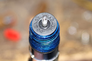
Remove the plastic part labeled "DO NOT REMOVE". It just pulls right off.
using a thin screw driver placed in one or both of the holes you see above. Push down or if needed lightly hammer the batteries out. DO NOT hammer directly on the plastic switch. The switch assembly will push all the way through the tube. Once you get the batteries out (if you get them out). You will need to clean out the tube. Use a small file, a hone, brass bottle brush, or whatever you can find that will work. Rinse out the tube and thoroughly dry it. Check that the silver tab is clean, then push the switch assembly back in place as you see it above. Replace the part marked "DO NOT REMOVE". Install the bulb and clean it off with alcohol. Reassemble the rest of the flashlight with new batteries.
VOILA!
10/02/2013
Blonder Tongue FM only R-20
Got this off of the shopgoodwill auction site. It is FM only and the design is like a Granco 620U I have, but the speaker is WAY smaller and on the back of the radio.
Here it is, as I got it, quite dirty.
And after I recapped it, replaced the failing Selenium Rectifier with a silicon diode, and cleaned it up.
Here is the Schematic
9/29/2013
Heathkit V-7A VTVM
Another Goodwill find. 2 VTVM's, a heatkit tube, and a Bell and Howell transistorized.
The Bell and Howell had major problems. A blown High tolerance resistor and one of the selectors was broken, so I parted it out. The Heatkit, however is fixable, it needs new capacitors and that is all.
9/26/2013
Nikko STA-5010
This is a Nikko STA-5010 from
goodwill.
This is a tricky unit to get sound out of on the goodwill test bench. I tried getting it working in store but no luck. However I took a chance for the low price and bought it. Instead of having to just get the speakers selected right, you have to do the following to get sound out of it:
hook up your speakers
Select your speakers
set the Tape selector to Source
and then! on the back of the unit change the switch that reads "Pre & Main" to "Connect".
This is very likely the reason it was still there when I got to the store, since I saw at least 2 flippers prowling the aisles.
All Lights work.
This stereo sounds great and I am not sure why it was donated. It is clean, a little dusty inside, I used deoxit on the volume control before turning it on so I am not sure if was scratchy. Oh well mine now! I will not be doing any replacing of parts on this unless it develops a problem.
9/23/2013
Heathkit GR-11
From Shopgoodwill.com. Needed a recap, and the 17c9 tube replaced. While cleaning it with denatured alcohol I accidentally removed the Heathkit silk screening from the front.
Picture taken before the recap.
The unit needs an antenna but gets really good reception. Speaker is a little small. I may put it in a new cabinet later and give it a better speaker. All the plastic standoffs were broken, but I found them inside the radio and epoxied them back on.
9/18/2013
That's some mighty fine police work, Lou
Got a call this morning at 6:15am. Unknown number. I answer and a man asks to speak with ****. I'm like "there's no **** here". He says "This number does not belong to an older woman with a walker?"
Wait what?
So somehow when the police report was made they put my number for the number that was on the note. So I gave the "detective" the correct number and we will see what happens.
9/14/2013
Old Woman is a Thief
What is this world coming to when strange old women come to your house, fish around in your mailbox and thieve your wife's rolling crate!
Oh and before she does that she leaves a note at the base of your security door with her phone number.
Yesterday my wife comes home and discovers the rolling crate she had recently purchased is gone. I searched the events on the surveillance system and found the following:
If you aren't interested in watching the whole thing:
she comes up our drive way. Looks at our stuff, rings the doorbell and snoops in the mailbox.
she then snoops some more and goes around to the side of the house.
she returns and writes a note that she places in our security door in a location we would have NEVER found.
She empties the crate folds it up and puts it in a plastic bag and takes off.
Today I got home about 6:30pm Called the police non emergency line. Burned a CD of the video. The officer showed up about 7:45 he was here about 30 minutes. He asked what I wanted to do? I wanted to press charges. He watched the video and wrote up a report and said that he did not think anything would come of it. I said "that's fine, since she may be doing this to other people I wanted something on file". I gave him the note and the cd. will they call the number in the note and pursue this? probably not.
So once again... as long as it is not particularly an expensive item that gets thieved, and you do not get personally caught, crime does pay.
9/12/2013
Zenith Z374 AM/FM Clock Radio
Picked this up at goodwill. It was sitting on the test table plugged in. I did not even test.
I just bought it. I took it home and initially could not find anything wrong with it.
I did notice one major issue. FM would quit working and you would have to switch from AM to FM to get it back. Then it would drop out again.
I tested all the tubes and found that the 17ew8, and 12be6 were week. The 35c5 was intermittent and probably the reason FM would drop out. replacing all fixed the problem. The only issue remaining is that the alarm function of the switch does not work. I will have to troubleshoot that later.
9/09/2013
Eico 377 Signal Generator
Snagged this at a goodwill for an exorbitant price. It did not work, but that was to be expected.
It will need all new capacitors, of which I have already started working on. This thing has more electrolytic caps than anything I have worked on before.
I counted 4 discrete caps and 2 dual section capacitors for a total of 8 electrolytic caps and 3 paper caps.
I ran out of 20uf capacitors and had to order more. I also replaced 3 out of spec resistors.
Subscribe to:
Posts (Atom)