7/07/2015

Small bench power supply for Transistor radios

I got really bored yesterday so I built an adjustable regulated power supply based on the schematic I posted.

I had been using batteries and battery packs with clip leads to power transistor radios so I needed to build this anyways.

I have a Lambda LP-532-FM Adjustable 40 volt 3 amp regulated power supply, but it is way to big and heavy for my bench.

So I built this:


I built it in about 5 hours from stuff I had floating around my shop:
A project case.
rubber feet.
old power cord and strain relief.
A transformer that outputs 28vac.
15 volt dc meter.
2 amp bridge rectifier pulled from some electronic device.
2200uf 50v electrolytic cap.
.1uf 50v film cap.
120 ohm resistor.
5k pot (I did not have a 3k).
Knob.
LM317T adjustable voltage regulator.
heat sink.
Perf board.
Neon lamp.
fuse holder.
1 amp fuse on the output side of the transformer.
old SPST power switch.
1 tie point.
Some terminals.
There is still room for a milliamp meter.
There is a jumper so I can hook in my DMM as a milliamp meter.

The maximum voltage output is about 35 volts but I will not be using it over 12 volts. The el cheapo DC volt meter is pretty accurate.

I checked the heat sink last night while powering my Ray Jefferson 630rdf and noted that it was indeed too small. I rectified that problem but then broke a lead on the LM317T and had to get a new one this morning.

I think the new heat sink should be more than adequate, no?
I mounted the LM317T to the heatsink with non conductive thermal material (otherwise the case would have DC voltage on it) it seems to be working fine and not getting hot.

Here is the Schematic:

7/03/2015

Westinghouse H126 "Little Jewel" Refrigerator radio

I bought this several months ago and shotgun recapped it, since almost all the paper caps were split open.
the guy who owned it was a "TRF man" and did not know anything about regenerative radios. :? whatever.

It worked fine for about 5 minutes or so, then started acting up, with garbled audio and only being able to sort of tune one station, but when you would stop moving the tuning dial it would lose the station or at least that's what it sounded like.

Months pass and I let it sit on a shelf, today I decided to start anew. I went throught the radio and checked the resistors, replaced a few out of spec. I thought maybe the problem was with the oscillator so I replaced a 47pf cap related to that. cleaned the 12sk7 and 12sa7 sockets, freed up a trimmer cap that was a little rusted. changed out the antenna wires, tried a different antenna, but nothing really made a difference.

then... I was going through the radio with my signal tracer, and not really being able to trace an RF signal I decided to make sure the AF was working, I was getting the same audio from the signal tracer as I got from the radio, until I placed the probe on the center pin of the volume control. All of a sudden I got clear audio from both the signal tracer AND the radio, AND the tuning started working. If I removed the ground wire of the signal tracer from the radio chassis and touched the center pin of the volume pot it went back to the way it was.

I spent most of the day working on it, and after replacing all of the original mica caps, I found that if I placed a resistor to ground in certain places the audio would return. I thought about this for a while and realized that all the components in question went through the volume pot to ground.

I pulled the volume pot and opened it up, this is what I found.
 It is hard to tell from the above picture, but the carbon is missing from the last 3/8" of the pot.

I did not think I had one so I took a break and went over to my brothers house for a while.
When I came back I looked though my stash of pots with switches and low and behold I had the exact replacement a 500k pot, with a switch AND a 100k tap.

I installed it and it work fine.

The last problem was that the original speaker was trashed.

I found a usable speaker, drilled the bracket off the back of the old speaker, attached it to the new one and mounted the speaker.
 I also made a new mask for the speaker and glued that and the speaker cloth to the speaker.

I repainted the sides and did an alignment.
 good as new.

5/30/2015

Bose AWR1-1W Refurbish

I picked this up a while ago from goodwill. It's missing the remote, battery cover, and the AM antenna, although I have both of these from another one of these I have. It's main issue was barely audible sound and a faint display.


First step in refurbishing is to remove the 4 screws on the bottom. Carefully seperate the black bottom from the remainder of the radio.
 unplug the 2 connector from the front J102 and J103.
and the speaker connector.

Remove the 4 screws from the plate on top of the power transformer, and the 2 connectors going to the board. Remove the power transformer, and equalizer board from the main board.
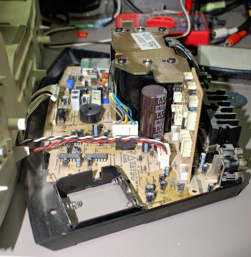
In the pictures above you will see some discoloration on the main board, that is capacitor juice from the electrolytics. ALL of the electrolytics (except maybe the large 10000uf cap) will have to be replaced, including on the equalizer board, and under the shielded area where the 7.2mhz crystal is.

Some people may not know this, but the Bose radios are always on, the audio is just muted when you press the on/off button. So your Bose wave radio may have been on constantly for 20+ years.

Once the transformer and equalizer are removed, disconnect the battery connectors from the box to the board, they are just pressed in place. The board can be removed just by releasing a couple of small black tabs.

Here is the back side of the board.
First thing you need to do is get some denatures alcohol and a paint brush. spray down the board where the cap juice is, give it a scrub and spray down again. then blow dry with canned air.

Once that is done begin replacing the electrolytic capacitors. I pick one value find and mark all of that value and then replace them. I mark the tops of the caps to make it easier to tell which ones I replace. You may smell a fish odor when desoldering, that is left over cap juice YUMMY!

WARNING!
be very careful of the traces on the circuit boards, they can easily be broken or the pads can break off when removing the caps. I broke one today, and fixed it with a small length of phone wire.

I started with the 10uf 16v caps, I replaced them with 16v, 35v, or 50v since that is what I had.

main board Electrolytic caps used in this radio
22 - 10uf 16v
4 - 1uf 50v
1 - .1uf 50v
4 - 0.47uf 50v
1 - 2.2uf 50v
3 - 3.3uf 50v
3 - 4.7uf 35v
4 - 47uf 16v
2 - 47uf 50v
3 - 100uf 16v
3 - 100uf 25v
1 - 220uf 16v
1 - 470uf 35v
total 52

This is the second one of these that I have found. This information is for the Generation 1 Bose wave Radio, the other radios have different circuit boards.

I was very careful and only broke one trace, but I did mess up about 4 pads and had to do some "fancy" soldering. I double checked the polarity of all the caps (fixed one) and powered it up. It works just fine. The next step is to recap the display board.

To get to the display board, use a small screw driver in the 4 square holes on the bottom of the main case.
 You will then be able to remove the front cover.
To remove the control panel, carefully pry up on the back of the panel and when it is about 1/4" pulled up, hold the display board in place and push the control panel forward to unplug it.
To get the panel out, pull the speaker wires partially up through the hole in the case, the panel will tilt forward and can be removed. There are no screws in it, but there are 2 pegs that fit in holes on the circuit board.

Electrolytic caps in the display board
2 - 1uf 50v
1 - 4.7uf 35v
2 - 47uf 16v
1 - 220uf 6.3v

All the caps on the display board are very short so mounting replacements can be a problem. They can only stick up as high as the display, so some may have to be bent over.

Make sure to clean the green plastic lens as it will usually be filthy.

3/14/2015

hallicrafters S-40A The Correct way to string the Band Spread Dial

If you have a hallicrafters S-40a, you may notice that stations do not tune in correctly, or it will not align properly unless the band spread knob is at 100. If this is the case then your band spread dial string is run incorrectly. When the band spread knob is at 0 the tuning cap plates for that should be fully open.


Sams, and hallicrafters manuals show something like this:

Yup the sams and hallicrafters diagrams are both wrong.
It needs to be run like this:
 
 Here is a link to the corrected sams.

2/25/2015

eudora was unable to update the system registry

If you run Eudora 7 like I do, and windows 7 or later, you may get this error:
"eudora was unable to update the system registry"

here is how I fixed it.

Eudora is trying to see what the default email client is, and may want to change it, even if you tell eudora not to check, it still checks. Windows 7 has severe protection on the registry.

Open Regedit.
navigate to:
HKEY_CLASSES_ROOT\mailto\shell\open\command

If you cannot, you will have to take ownership or give yourself or everyone full control of the shell key and several sub keys. 

you may have to hit f5 or try to create a sub key to get the open and command keys to appear. do not change anything. open eudora and it should no longer give the annoying message. If this does not work do not contact me for further help, it works for me.

1/21/2015

hallicrafters S-40A

A couple of weeks ago I went to a local swap meet that happens on the first Saturday of each month (only in winter), here in Phoenix. It is called the Thieves market. It's kind of a hipsterish, crafter, American pickers type of swap meet, where people bring "antiques" and other stuff you generally don't see at swap meets around here anymore. When we got to the swap meet and were parking I spotted this from the car.

I know it's not anything super neat and special but I figured "what the hey". I asked the guy how much and was shocked when he didn't want an arm and a leg for it.
I bought it, and since it was heavy I took it straight to the car. It even came with a set of Trimm headphones. I won't be able to start working on it for a couple of weeks as I am in the middle of completely redoing my computer/hobby room. But today (after checking it out carefully) decided to take a chance and see if it works. First thing I did was inspect it. I oiled the bearings in the tuner and other parts. I cleaned all the pots, and had to open the power switch and spray deoxit in it as the switch was not making contact.
It's not in this picture but when I opened the top there was a cord inside. Not sure if it was from this radio as it did not match the cord wires coming out the back. I didn't find any cracked or burned resistors. no blown or split capacitors. no sign of anything singed.
I was confused since the operating manual, and sams shows an 80 tube for the rectifier, but the hallicrafters service manual shows a 5y3gt. This one has an 80.

I replaced the power cord.
I brought it up very slowly on my variac with my dim bulb tester. Although it says it can operate between 105-125vac I kept it at 117vac. The lights came on the heaters lit, and nothing... no hum, no buzz, no hiss, nothing... :?

Oh right, ANTENNA! hooked up my random/long wire and there it was AM radio. I went through the bands and kept an eye on the electrolytic cap, and the transformer to see if they were getting warm, but they did not.

So the dang thing works just fine. Not wanting to tempt fate I shut it down after about 15 minutes.

I will start recapping it sometime in the next month.

10/18/2014

Cheap Small Portable Generators

There are many small very cheap 2 cycle portable generators that you can buy. They are sold under several makes and models:
Chicago Electric 66619 from Harbor Freight 800 to 900 watt
Triron 1200
Pulsar PG1202S
PowerPro 56101
TradesPro 836758
ETQ TG1200
Coleman CM04101
And many many more.

Many of these have one thing in common, they are cheap crap/utter turds. They all look pretty much like this:

But these turds can be polished.

If you buy one of the above generators (or one like them), before you start it up I recommend the following:
Replace the spark plug with an Autolite 65, or 64, or an equivalent type spark plug.
Gap the spark plug to between .028 and .031.
Torque the spark plug to 25 foot pounds or 360 inch pounds. The spark plug that comes with them are often cheap junk and not gapped correctly.
Remove the gas tank.
locate every connector that looks like these:
and make sure they are tight, use pliers to pinch them tight if not (the slot end, not the wire end), as they will vibrate off if you do not tighten them.
Inspect the fuel line, if it looks like smooth plastic and possibly has a mold seam, replace it with real fuel line. I would recommend replacing it anyways. Many of these use a plastic fuel line that will swell, split, or deteriorate in a very short time.
replace the fuel line hose clamps with good ones.
remove the fuel valve and replace the gasket pointed to in the picture below with a gasket or washer that holds up to gasoline. The washer installed is plastic and will not last long.
re-assemble the generator, mix up a batch of fuel at 40:1 not 50:1 the extra oil will help with lubrication and should not smoke any more than usual.

Put gas in the tank, wait about 5 minutes for the carburator bowl to fill, and start the engine, with the choke full on, move the choke over to run, and connect a 200 watt load to the generator wait 5 minutes. Using a volt meter check the voltage (under load) it should be 120 volts AC if not adjust the screw in the recess shown in the picture below (the red arrow). If the engine sputters when doing this adjust it as close as you can to 120 volts AC and the engine still runs smooth. let it run for several minutes and monitor the voltage, adjust again if necessary.
The green arrow points to the fuel valve.

Drain the gasoline if the generator will go unused for more than a couple of months. You will have to remove the gas tank and fuel valve to do this. If you do not, the gasoline can turn in to varnish and clog the fuel valve, line, and carburetor. Leave the fuel valve open while it is being stored and the gas cap loose to allow the remaining gasoline to evaporate.

10/09/2014

Raleigh Super Sensitivety All Transistor

Got this one off of someone at www.antiqueradios.com. It is made in South Korea and is from the mid 60's. It runs off of 4 D batteries or an external AC adapter.
It did not work when I got it, I opened it up and found that the wires going to the batteries had broke loose. I re-soldered them and it worked. I changed out all the electrolytic capacitors anyways as they were 50+ years old and some may have been leaking. It has a very long almost 7" ferrite antenna and is quite sensitive. I think it may have been manufactured by Gold Star as the general design is very similar to other radios made by them at that time. Probably OEM'd for some other company. I mostly just like the design.

10/07/2014

RCA 36X

Picked this up at an Arizona Antique Radio Club swap meet. Many of the radios there were priced a bit high but this one was reasonable and had been completely restored.
 It had one major problem, it didn't pick up anything but static and crackled when the tuning knob was moved.
I found that the plates in the tuning capacitor were either slightly corroded, touching, or had tin whiskers. I carefully cleaned the plates with fine grit sand paper, and now it works perfectly. This is now the oldest radio I own circa 1941.

10/04/2014

hallicrafters S-120 Goodwill find

Picked this up recently at Goodwill for very cheap. I cleaned off the hobo sweat. It hummed at power up. I recapped it but it still hummed.
 I did some poking around and found that the floating ground was miss-wired.
It's really just an updated S-38 and performance is about the same.


8/16/2014

Harman Kardon hk 680i


Picked this up Thursday at goodwill. Tested it in store and noted the left channel out.

It's a Harman Kardon hk680i.
Top

Bottom

Got it home, opened it up and did a thorough look through. Did not see anything unusual until I looked at the bottom.
Yes those are 2 traces cut with a dremel tool. I jumpered the cuts but that did not make a difference. The left channel stayed just barely audible. Right was normal. removed the jumpers as this could have been a factory mod or maybe something done after market to fix a problem. There was nothing in the service manual about it.

Some research brought me to a thread on Audiokarma regarding the hk690i and that they have problems with dirty switches and pots. Deoxit did not help, but when I took some of the stereo apart I found a broken wire. Re-soldered that and viola it works. HOWEVER in taking it apart I broke the memory presets led circuit board that a previous owner had already broke and "fixed".

Re-soldered that and put it back together but now it has a new problem. It randomly looses lock on station goes to static and the tuner display does random stuff. I will maybe try and figure out whats wrong with it later. Definitely can't sell it as working. It sounds good contrary to some reviews on Audiokarma of it "sounding thin".


I later removed the memory presets LED board and the stereo works just fine but there is no LED indication as to which preset is selected. big deal.

This stereo has some interesting features.
An adjustable FM muting pot on the back, and a stereo separation adjustment labeled "Blend" that goes from Mono to Stereo. Kind weird to see on a stereo from the early eighties. I would expect it on something from the MPX days of the 60's.

7/12/2014

Make your own Serial Cable for the Uniden Bearcat BC296D

I recently acquired the scanner listed above, sans serial cable. I sent off a note to Uniden asking for information on the cable and where I might get one.

Their reply (which took a while) was basically (paraphrasing) "we don't carry it anymore, don't bother us".

I attempted to find one on line elsewhere and did succeed but being the cheapskate that I am, I did not want to pay $30+ for one.

No one makes a USB cable that will work with this scanner, it is serial only. There are some that look like they will work, but the scanner connector is for a later model scanner. The cable end that connects to the scanner is not a standard connector. Trust me the standard small usb connectors will NOT fit. Do not attempt to use any regular USB cable to connect the computer to the scanner it will fry the scanner and could brick your computer.

I found a website in Russia that had some vague instruction on how to make the cable, I refined those "instructions".

You will need:
1 - USB Cable for the Fuji FinePix 2300, 2300Z, 2600, 2600Z, or 2500 camera, ebay has them for about $7.50 (including shipping).
1 - 9 pin female serial connector.
The information below.

This is the connector on the scanner (pin numbering marked). The Fuji camera cable connector is in the picture further down.
Cut the large "type A" connector off of the USB cable, solder the 9 pin connector to the USB cable using the picture below as a guide. I would double check the information below as wire colors may not be the same. I used the continuity function on my volt meter to verify everything was correct.
Now for the bad news. The Serial cable may only work with a real serial port, not a USB to Serial. My U232-P9 converter would not work. It would ALMOST work, but the Uniden software is flaky and does not have much in the way of settings. I got mine to work with a laptop I have that has a real serial port.
Uniden software Settings are any one of 4 BAUD rates:
9600
19200
38400
57600 Delay time setting was set to 0.

Configure your port in device manager to the same BAUD rate, 8 data bits, no parity, 1 stop bit, no flow control.

check the Uniden scanner manual on how to configure the scanner with the correct BAUD rate, page 60.

The manual, and software are still available from Uniden to download, and there may be other third party software that can be purchased.

5/21/2014

What will become of us?

My wife asked me that the other day, this is what I told her:

Well... eventually we will die, and be buried (maybe). We'll lie in the ground for several hundreds or even thousands of years. A group of archaeologists will dig us up and make wild suppositions on our health, wealth and ancestry.

We will be cataloged and photographed, x-ray'd and DNA sequenced, then placed in storage, where occasionally graduate students will pull us out and make more outlandish conclusions about us. Eventually we will be discarded or lost, until one day billions of years in the future when the sun turns in to a red giant and envelopes the earth our molecules will circulate in the sun until we are blown off in to a planetary nebula.

Our molecules will wander through the galaxy until they are drawn in to the atmosphere of a planet in some other solar system, where biological life forms will ingest and excrete us, until we make it in to a higher life form that says "blorg... What will become of us?"
...
...
...
"WOW! you've really thought this through?" She said.
yes...yes, I have.

5/18/2014

My First HD Radio

I have been looking in to getting an HD radio since I first heard found out about them a few months ago... yes I know they have been out longer than that, I just did not pay attention.

However it seems I missed the boat and all the inexpensive HD radios have been sold and there aren't many out there of decent quality and of reasonable price.

I was tipped off to an ebay auction for a Directed dmhd1000i hd radio for $25 bin "free" shipping. Not including shipping the unit cost me $11.

I just got it today. It was NIB and looks like it was never opened. It was also marked "Not for Resale".

This is not a standard table top radio. it is meant as an add on to a car stereo.

Here is what came in the box:
The radio unit.
Control panel with about 10 feet of cable.
a remote.
2 antenna adapters.
mounting brackets.
and a billion miles of wire to hook it in to power.

To test it I threw it on my bench and hooked it up to a 12 volt power supply. although it has an interesting way that it has to power up.

There are 3 wires Yellow, Red, and Black. You hookup the Yellow to a constant power source, the black to ground and the red to a power source that is switched.

To get it to power on I hooked it up with black to minus, yellow to positive, and then used an alligator clip to connect red to positive after the yellow was connected. If you do not do it this way the unit will not power up from the display.
Audio output is rather low but way more than strong enough for my homemade amplifier that has a 12ax7 input and single ended 35c5's for output. I have to turn the volume way down for comfortable listening. There are no specs on what it's audio output is.

There are 2 modes of audio out, one is through stereo RCA connectors and the other is through RF modulation through the antenna output to any frequency in the FM band. I have not tried the latter.

The unit is currently connected to a Discone antenna above my roof line.
FM analog sensitivity is excellent, I can pickup kcdx a 2700 watt xmitter 67 miles away (not HD) with a reasonably good signal. kvit a 10 watt station about 12 miles from me that is understandable (not HD).

FM HD reception is excellent for ALL stations in my area that have it. The unit takes about 7 seconds when tuned to an analog station to lock in the HD signal. Once locked in, the transition to HD is noticeable as the music quality improves, the noise floor almost disappears, and the volume drops slightly.

As for AM Analog sensitivity is excellent, kazg comes in great using either my discone or my 67' random wire antenna kazg is a 5000 watt daytime and 50 watt night time station. After sundown it still came in great and is 4 miles away from me. Most of my AM radios can barely get this station after dark.

There are only 3 AM HD radio stations in my area (that I could find). 2 are talk and 1 is a religious music station. 550 would not lock in after sundown even though it did earlier. The religious station locked in but sounded terrible. I think this is because of the recording quality of whatever they are transmitting since it sounded terrible in analog. The other talk radio station on 910 comes in very clear on HD or analog. Time to lock in seemed to vary for AM stations but was about 7 to 15 seconds. AM HD lock on was similar to FM with static and noise all but gone and sound quality improved.


On the underside of the daughter board with the large chip on it, there are several tiny LEDs that blink rapidly at a regular rate.

When I first powered the unit on the audio sounded not very good with what I would describe as clipping or static, but that has since disappeared, and all stations sound fine. I have not noticed any compression artifacts in any of the Digital streams. After about 2 hours use the unit is rather warm, about 115° or so.

My plan is to mount the DMHD-1000 either in a box or somewhere near my Silvertone 7407, with the control panel mounted somewhere that I can see it, and use the remote to control it.

I found that these suffer with a problem on the RCA connectors of over modulation.

There are 2 fixes for it, 1 I have confirmed works and the other I have not tried.

The first is to use the FM modulation mode, I have not tested this. The other which I can confirm works is to connect the ground tabs of the RCA connection to the metal case, and on to ground. This is the only problem I have found with my unit. Once I grounded the RCA shields the audio signal cleared up completely.