
11/27/2015
More El Cheapo FM mp3 players
Here are 2 more AM radios I converted to FM/mp3 players.


Motorola


Magnavox


11/01/2015
El Cheapo AA5 mp3/FM mod
I had purchased several of these FM radio mp3 players:

They run off of 12vdc, and have inputs for SD memory, USB sticks, and possibly even a hard drive. There is also a line in, FM stereo receiver, and stereo out to drive an amp or headphones. Some units have blue tooth capabilities.
I have wanted to add them to a nothing special AA5 radio for a while, but most AA5's don't have a front panel with enough space for one.
Recently I was inventory my small hoard of radios some of which I got when I first started in this hobby, and was buying whatever I could find just to get experience with fixing them. I picked up 3 radios off of ebay for real cheap and saved even more money with local pickup.
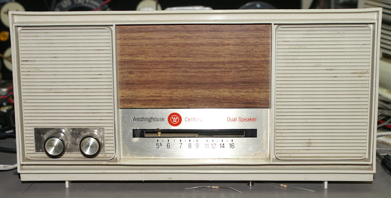
 The Zenith (with the stain) on the left I parted out for reasons I do
not remember, The Motorola is very plain Jane and reminds me of a block
of white chocolate, and then there is the Westinghouse.
The Zenith (with the stain) on the left I parted out for reasons I do
not remember, The Motorola is very plain Jane and reminds me of a block
of white chocolate, and then there is the Westinghouse.
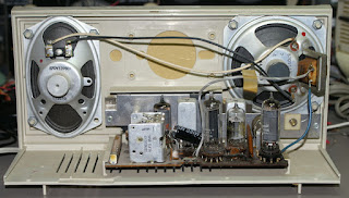
 The "Chassis" (V-2466-x) is used in 17 models, there is a ton of room
inside. This one had an option for a clock radio covered by faux wood
grain.
The "Chassis" (V-2466-x) is used in 17 models, there is a ton of room
inside. This one had an option for a clock radio covered by faux wood
grain.
 My plan is to cut out a hole to mount the player in the middle of the
faux wood grain, connect the output of the player in to the audio amp of
the radio through a switch, and supply an input for the line in, and
possibly an output for headphone. I will also mount a small wall wart
inside the radio to power the player and be switched on by the radio. I
will use it for a while and then try and sell it.
My plan is to cut out a hole to mount the player in the middle of the
faux wood grain, connect the output of the player in to the audio amp of
the radio through a switch, and supply an input for the line in, and
possibly an output for headphone. I will also mount a small wall wart
inside the radio to power the player and be switched on by the radio. I
will use it for a while and then try and sell it.
I Started working on it by removing the chassis and speakers so I could give the plastic a good cleaning.
 I had something serendipitous happen when I removed the chassis I found
out that the front plate was only partially glued in so I removed it.
I had something serendipitous happen when I removed the chassis I found
out that the front plate was only partially glued in so I removed it.

 With the front plate off I will be able to cut holes in it a whole lot easier.
I drew up a template in autocad and printed it one to one.

Another serendipitous thing is that the dial pointer/needle had a protective covering that someone may have forgot to remove when it was built. removing it greatly brightened the dial pointer.
I cut the hole out of the face plate with a nibbler and then cutout the plastic with nippers and the nibbler.
here is the player temporarily mounted:

 I rewired the player since I could not find any connectors like the ones it originally came with:

I did some searching and found that the unit will work with anything from 5 to 12 volts. There is a 5 volt regulator right after the +12vdc connection.
I am going to use a 9vdc 700ma wall wart since the unit will need 500ma to power usb devices.
I cut the trace on the board between the 3.3 meg resistor and the pot, I installed a switch between it
Instead of installing a transformer internally, I installed a power socket for a 9vdc wall wart


I installed the 3.5mm input jack on the front as the plastic was too thick to do it on the back or side.
 It sounds just fine and reception is excellent.
here is more info to help people out:
 If you want to try this look for the following:
Power switch
voltage regulator (yellow line points to it in pic below)
comes with the wires and connectors.
 I have ordered some of these (of different types in the past). Some come
with a voltage regulator some do not. I found out the hard way by
blowing one up (with no VR) when I accidentally put in too much voltage.
I have ordered some of these (of different types in the past). Some come
with a voltage regulator some do not. I found out the hard way by
blowing one up (with no VR) when I accidentally put in too much voltage.
The LM7805 can output 5volts +/- .25vdc 1amp if I am reading the spec sheet correctly it can actually handle up to 35vdc input.
Some of the listings claim it can be used to charge a phone, but one review on a website claims that it will fry your phone, it did not occur to me to use this as a phone charger. I am not sure what the port in the picture above marked "in" and "Charging port" is for since that type of connector is usually used to connect a device to a computer. I am hesitant to plug something in to it.
The unit will scan and store all stations it can pickup to saved presets, it has very high gain for such a little radio. There is an EQ function which seems to only be for mp3's and not the radio. It has a clock but I cannot figure out how to set it. I have not found a manual for it so far. It has a small amp built in that puts out about 1 volt max so a preamp is needed for some applications, the 12av6 worked fine for that. There is a built in volume control as well. Thankfully the boards are marked or else it would be very difficult to hook these up properly.
Sound output in this radio is ok considering the type of speakers, when I tested it with a 200mw amp and nice 8ohm speakers it sound just as good as any small stereo you could have.
The remotes for these are all the same except that the buttons may be marked different, I have 2 different units and the remotes work on either one, but on one the EQ button is scan up, pressing it does a scan up on this unit. other buttons labeled differently operate the unit the same as my other one with different markings.
The radio is a Westinghouse cr-510. Good luck finding one.
other models:
cr-500
cr-501
cr-515
cr-520
cr-521
cr-530
cr-531
cr-535
cr-536
h-200t5
h-201t5
h-205L5
h-210L5
h-211L5
h-215L5
h-216L5

They run off of 12vdc, and have inputs for SD memory, USB sticks, and possibly even a hard drive. There is also a line in, FM stereo receiver, and stereo out to drive an amp or headphones. Some units have blue tooth capabilities.
I have wanted to add them to a nothing special AA5 radio for a while, but most AA5's don't have a front panel with enough space for one.
Recently I was inventory my small hoard of radios some of which I got when I first started in this hobby, and was buying whatever I could find just to get experience with fixing them. I picked up 3 radios off of ebay for real cheap and saved even more money with local pickup.


I Started working on it by removing the chassis and speakers so I could give the plastic a good cleaning.
Inside the case after cleaning.


The front plate after some cleaning.

I drew up a template in autocad and printed it one to one.

Another serendipitous thing is that the dial pointer/needle had a protective covering that someone may have forgot to remove when it was built. removing it greatly brightened the dial pointer.
I cut the hole out of the face plate with a nibbler and then cutout the plastic with nippers and the nibbler.
here is the player temporarily mounted:


I did some searching and found that the unit will work with anything from 5 to 12 volts. There is a 5 volt regulator right after the +12vdc connection.
I am going to use a 9vdc 700ma wall wart since the unit will need 500ma to power usb devices.
I cut the trace on the board between the 3.3 meg resistor and the pot, I installed a switch between it
Instead of installing a transformer internally, I installed a power socket for a 9vdc wall wart

Here is the back.


here is more info to help people out:

Power switch
voltage regulator (yellow line points to it in pic below)
comes with the wires and connectors.

The LM7805 can output 5volts +/- .25vdc 1amp if I am reading the spec sheet correctly it can actually handle up to 35vdc input.
Some of the listings claim it can be used to charge a phone, but one review on a website claims that it will fry your phone, it did not occur to me to use this as a phone charger. I am not sure what the port in the picture above marked "in" and "Charging port" is for since that type of connector is usually used to connect a device to a computer. I am hesitant to plug something in to it.
The unit will scan and store all stations it can pickup to saved presets, it has very high gain for such a little radio. There is an EQ function which seems to only be for mp3's and not the radio. It has a clock but I cannot figure out how to set it. I have not found a manual for it so far. It has a small amp built in that puts out about 1 volt max so a preamp is needed for some applications, the 12av6 worked fine for that. There is a built in volume control as well. Thankfully the boards are marked or else it would be very difficult to hook these up properly.
Sound output in this radio is ok considering the type of speakers, when I tested it with a 200mw amp and nice 8ohm speakers it sound just as good as any small stereo you could have.
The remotes for these are all the same except that the buttons may be marked different, I have 2 different units and the remotes work on either one, but on one the EQ button is scan up, pressing it does a scan up on this unit. other buttons labeled differently operate the unit the same as my other one with different markings.
The radio is a Westinghouse cr-510. Good luck finding one.
other models:
cr-500
cr-501
cr-515
cr-520
cr-521
cr-530
cr-531
cr-535
cr-536
h-200t5
h-201t5
h-205L5
h-210L5
h-211L5
h-215L5
h-216L5
10/18/2015
Datsun Nissan Hitachi A-1561 A-1551 Stereo Car Radio
I picked up one of these at a swap meet recently.
I spent a lot of time trying to find information about this radio on line to no avail. It took me a while to figure out the pinouts of the radio connector.
So you don't have to spend the several hours trying to find it, here are the pinouts.
 The metal case is ground for the 12 volt supply.
I spent a lot of time trying to find information about this radio on line to no avail. It took me a while to figure out the pinouts of the radio connector.
So you don't have to spend the several hours trying to find it, here are the pinouts.

9/20/2015
Multi plug Remote control module from a fan
I had a Pelonis remote controlled fan that I got tired of having to
re-oil every year or 2. I was intrigued by the remote control unit, and
was curious if it could be re-used in some manner.
Here is the Control Board.

The fan it came out of had a rating of .45 amps. On the board is a 2 amp fuse. 3 LED's that indicate fan speed, and 3 LED's that indicate Timer length, 1, 2, and 4 hours. There is an IR receiver, and 2 buttons, 1 that cycles from off, through 3 speeds then off again, and one that cycles the timer length. A piezo speaker beeps when a button is pressed or it receives the IR signal.
Fan "speed" control works as follows. the Blue wire is common, Grey is low speed, orange is medium, and red is "STR" which I guess means strong? but is high speed.
When low is selected 120 volts is directed through the Grey wire and not the orange and red. Medium puts 120v though the Orange, but not Grey and Red, High puts 120v through Red but not orange or grey.
I decided to build this:

 It can switch between 3 1 amp loads.
See it in action:
Here is the Control Board.

The fan it came out of had a rating of .45 amps. On the board is a 2 amp fuse. 3 LED's that indicate fan speed, and 3 LED's that indicate Timer length, 1, 2, and 4 hours. There is an IR receiver, and 2 buttons, 1 that cycles from off, through 3 speeds then off again, and one that cycles the timer length. A piezo speaker beeps when a button is pressed or it receives the IR signal.
Fan "speed" control works as follows. the Blue wire is common, Grey is low speed, orange is medium, and red is "STR" which I guess means strong? but is high speed.
When low is selected 120 volts is directed through the Grey wire and not the orange and red. Medium puts 120v though the Orange, but not Grey and Red, High puts 120v through Red but not orange or grey.
I decided to build this:


See it in action:
7/28/2015
Makita 5092D saw converted to corded


I installed a jack in the bottom of the battery compartment for the cable I am using.

This will work just fine for the projects I may have in the future.
7/21/2015
Antique Radio Isolated Power Supply
A couple years ago when I got in to this hobby, I wanted to free up some bench space taken up by my Dim bulb Tester, a volt meter, variac, and other devices.

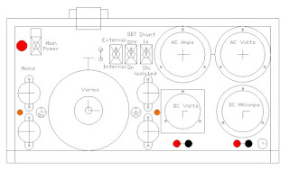
I wanted them to fit in a single cabinet. This is the first drawing I did in Autocad 2002. I began collecting the needed parts for it.
 The problem was that I could not find a decent cabinet that did not look cheesy or homemade. About a year ago I bought a B&K 1076 TV Analyst from a Goodwill for about $8. I do not ever intend to work on vintage TV's as they take up too much room. So I parted it out. I kept the case but it was only about 6 months ago that I decided to use that for the case. So I redesigned the device to fit in the new case. This was the final design.
 The hardest part was obtaining the front panel. Initially I was going to use a side panel from an old computer case, but could not cut the piece I needed out of it and still have it look good. So I called a local sheet metal shop and bought a piece of aluminum cut to the size I needed. I printed the layout on paper at 1:1 scale, then punched the centers of all the holes. I drilled the holes out, or in the case of the larger ones, I used a nibbler and dremel tool.


I wanted them to fit in a single cabinet. This is the first drawing I did in Autocad 2002. I began collecting the needed parts for it.


Here are most of the parts needed to assemble the device.


I painted the piece gloss black.

This is the case to the B&K 1076


It took about 3 days to do the actual assembly, and this is the final result.
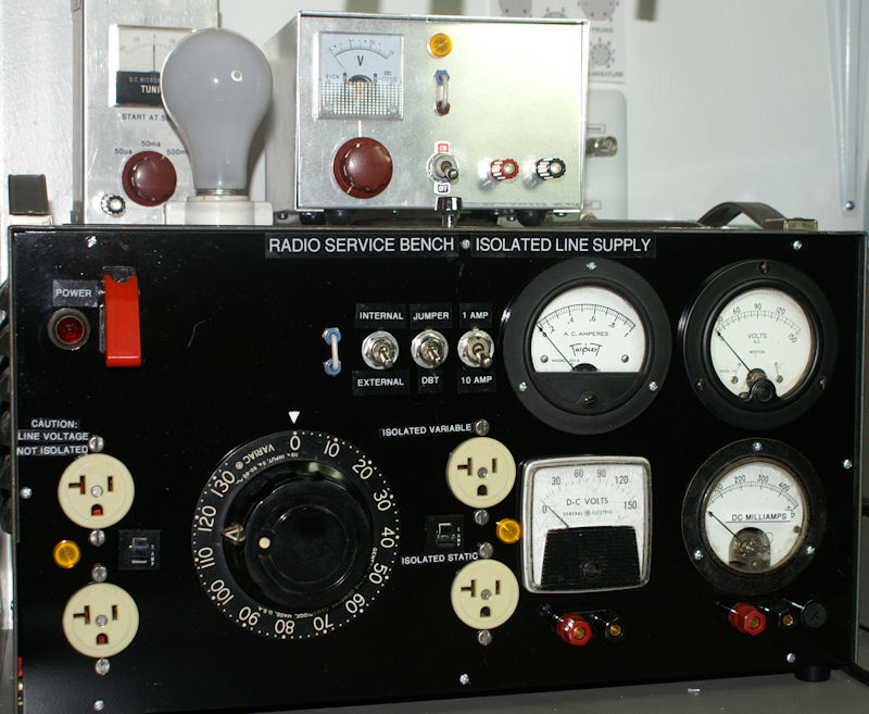
Some pictures of the inside wiring.


Here is a short video of it's operation.
7/07/2015
Small bench power supply for Transistor radios
I had been using batteries and battery packs with clip leads to power transistor radios so I needed to build this anyways.
I have a Lambda LP-532-FM Adjustable 40 volt 3 amp regulated power supply, but it is way to big and heavy for my bench.
So I built this:


A project case.
rubber feet.
old power cord and strain relief.
A transformer that outputs 28vac.
15 volt dc meter.
2 amp bridge rectifier pulled from some electronic device.
2200uf 50v electrolytic cap.
.1uf 50v film cap.
120 ohm resistor.
5k pot (I did not have a 3k).
Knob.
LM317T adjustable voltage regulator.
heat sink.
Perf board.
Neon lamp.
fuse holder.
1 amp fuse on the output side of the transformer.
old SPST power switch.
1 tie point.
Some terminals.
There is still room for a milliamp meter.
There is a jumper so I can hook in my DMM as a milliamp meter.
The maximum voltage output is about 35 volts but I will not be using it over 12 volts. The el cheapo DC volt meter is pretty accurate.
I checked the heat sink last night while powering my Ray Jefferson 630rdf and noted that it was indeed too small. I rectified that problem but then broke a lead on the LM317T and had to get a new one this morning.
I think the new heat sink should be more than adequate, no?

Here is the Schematic:

7/03/2015
Westinghouse H126 "Little Jewel" Refrigerator radio
I bought this several months ago and shotgun recapped it, since almost all the paper caps were split open.
 the guy who owned it was a "TRF man" and did not know anything about regenerative radios.
  whatever.
It worked fine for about 5 minutes or so, then started acting up, with garbled audio and only being able to sort of tune one station, but when you would stop moving the tuning dial it would lose the station or at least that's what it sounded like.
Months pass and I let it sit on a shelf, today I decided to start anew. I went throught the radio and checked the resistors, replaced a few out of spec. I thought maybe the problem was with the oscillator so I replaced a 47pf cap related to that. cleaned the 12sk7 and 12sa7 sockets, freed up a trimmer cap that was a little rusted. changed out the antenna wires, tried a different antenna, but nothing really made a difference.
then... I was going through the radio with my signal tracer, and not really being able to trace an RF signal I decided to make sure the AF was working, I was getting the same audio from the signal tracer as I got from the radio, until I placed the probe on the center pin of the volume control. All of a sudden I got clear audio from both the signal tracer AND the radio, AND the tuning started working. If I removed the ground wire of the signal tracer from the radio chassis and touched the center pin of the volume pot it went back to the way it was.
I spent most of the day working on it, and after replacing all of the original mica caps, I found that if I placed a resistor to ground in certain places the audio would return. I thought about this for a while and realized that all the components in question went through the volume pot to ground.
I pulled the volume pot and opened it up, this is what I found.
 It is hard to tell from the above picture, but the carbon is missing from the last 3/8" of the pot.
I did not think I had one so I took a break and went over to my brothers house for a while.
When I came back I looked though my stash of pots with switches and low and behold I had the exact replacement a 500k pot, with a switch AND a 100k tap.
I installed it and it work fine.
The last problem was that the original speaker was trashed.
I found a usable speaker, drilled the bracket off the back of the old speaker, attached it to the new one and mounted the speaker.
 I also made a new mask for the speaker and glued that and the speaker cloth to the speaker.
I repainted the sides and did an alignment.
 good as new.


It worked fine for about 5 minutes or so, then started acting up, with garbled audio and only being able to sort of tune one station, but when you would stop moving the tuning dial it would lose the station or at least that's what it sounded like.
Months pass and I let it sit on a shelf, today I decided to start anew. I went throught the radio and checked the resistors, replaced a few out of spec. I thought maybe the problem was with the oscillator so I replaced a 47pf cap related to that. cleaned the 12sk7 and 12sa7 sockets, freed up a trimmer cap that was a little rusted. changed out the antenna wires, tried a different antenna, but nothing really made a difference.
then... I was going through the radio with my signal tracer, and not really being able to trace an RF signal I decided to make sure the AF was working, I was getting the same audio from the signal tracer as I got from the radio, until I placed the probe on the center pin of the volume control. All of a sudden I got clear audio from both the signal tracer AND the radio, AND the tuning started working. If I removed the ground wire of the signal tracer from the radio chassis and touched the center pin of the volume pot it went back to the way it was.
I spent most of the day working on it, and after replacing all of the original mica caps, I found that if I placed a resistor to ground in certain places the audio would return. I thought about this for a while and realized that all the components in question went through the volume pot to ground.
I pulled the volume pot and opened it up, this is what I found.

I did not think I had one so I took a break and went over to my brothers house for a while.
When I came back I looked though my stash of pots with switches and low and behold I had the exact replacement a 500k pot, with a switch AND a 100k tap.
I installed it and it work fine.
The last problem was that the original speaker was trashed.
I found a usable speaker, drilled the bracket off the back of the old speaker, attached it to the new one and mounted the speaker.

I repainted the sides and did an alignment.


Subscribe to:
Posts (Atom)