12/11/2013

Knight Signal Tracer

Picked this up at hamfest Saturday for $15. it does not have the probe and I will be making one.

Before


I did a simple recap on it, which reduced the noise levels on the (non noise setting). I replaced the cord, mic connector, and added a fuse. I removed the nasty stained speaker grill and replaced it with some black speaker cloth and a box fan guard. I then gave it a lite bath.

The 6E5 Eye tube seems a little dim and I will look for a replacement at some point.

After

11/24/2013

General Electric Super Radio I

Never much cared for AM/FM only Transistor Radios, especially boring GE's. I had read many time on several forums about the GE Super radios. Today I found one at Goodwill. A Model 7-2880B Which is one of the first models. Many people claim it is very sensitive and a good performer, but I am often skeptical. My test of any of these claims is how well they can receive KAZG. KAZG is a Daytime only station that drops to 50 watts at night. I plugged this radio in, at the store which was about 12 miles from KAZG and it was after sunset. Normally any radio I try, will pick up either nothing or just barely get a signal. This radio has promise because it was staticy but listenable. The final test is when I get home. My house is about 4 or 5 miles from the transmitter. After sunset the station is very staticy with most radios. With this Radio the station sounds almost as loud and clear as most other radios do in the daytime (for the same station). It even beats my Zenith Royal 780 The top contender of the portable radios I own.
 The large speaker and tone controls are a plus as well.

I tested it one night and I was able to pick up KNX 1070 LA 372 miles from me, and KKOB 770 in Albuquerque, NM 338 miles from me.

11/17/2013

Refreshing The Fisher XP-9C Speakers Part III

Finally got a chance to work on these speakers again. I made a new frame for the speaker fabric. I was able to re-use the old fabric as it had not shrunk too much.
The picture below shows the frame under the covering because of the camera flash but it is not visible otherwise.
There is one final issue. one of the speakers has a problem with the "Fried egg" tweeters, they do not work unless pressure is applied to a specific point on their rims. I have them temporarily working with a pair of magnets. I will have to replace all of them at some point.

How do they sound? Great but, Very BASSY. Treble needs to be bumped a bit to compensate. I tested them with different records and CD's. They really like orchestral music. But sound good with Rock. They did not work well with my Beat Dominator CD. The bass was just a little too low for the crossovers. If I kept the volume at a reasonable level they could handle it, but turn it up too much and they cut out.

11/13/2013

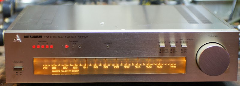
Replacing the Dial lights in a Mitsubishi M-F01 Tuner

I am writing this up in case anyone else is dumb enough to try it, and you want to know basically how to do it right.

The Mitsubishi M-F01 FM Tuner I got the other day had some burnt out bulbs, turned out 1 white bulb, and both green bulbs were out.

I made the HUGE mistake of removing all the screws on the faceplate to get to the bulbs.

HOWEVER! I did manage to get the bulbs replaced. I found that the old incandescent bulbs ran off of 9vdc and that they were all white bulbs with colored rubber covers, one bluish, and the other Green. The white light comes from the blue colored one and the green you can figure out yourself.

It is not necessary to remove the dial knob to remove the faceplate, it is not necessary to remove the faceplate (but I did) :oops:

When you remove the faceplate, the dial, and tuning knob fall out. Then the dial string unravels YAY! :shock:

In reality the only thing you have to do is remove the 2 screws that hold the circuit board in the picture below circled in red. Then carefully move the circuit board out of the way.

ANYWAYS... I don't have the bulbs and did not want to go on a quest to find some, plus I am impatient. But I did have these:
http://www.modeltrainsoftware.com/ledlights1.html

The LED's work on a wide range of voltages and it does not matter what polarity or if you have AC or DC. Being standard LED's they were also the same size as the old bulbs. The old bulbs were mounted on small circuit boards, three wires; blue, green, and Black. Blue for the white light, green for green light and black was ground.

I removed the little circuit boards and I connected 1 wire from the white LED to the Blue wire, one wire of the Red LED (I chose Red instead of Green) to the green wire, and then the remaining wires from both to the black. I used shrink tube as needed. I installed the bulbs in the dial with hot glue after verifying that they worked. I did this for both sides (there are 2 sets of lights).

I got it back together and restrung the dial.

Not on station!

On Station!
 

The only disadvantage to these LED's is that if you connect them to AC or unfiltered DC they may flicker juuuuuuuust on the edge of your perception.

I did not take any other pictures because I was too irritated and did not think I was going to get it back together.

10/29/2013

Refreshing The Fisher XP-9C Speakers Part II

After I received the non polarized electrolytics I replaced them on the crossover. I had to order extra 50uf capacitors as Parts Express did not carry 25uf caps. I put 2 - 50uf caps in series to get 25uf.
To make a good seal around the speakers I picked up some weather stripping. I wanted a good seal since this is an acoustic suspension system.
I used a hair dryer and a vacuum to pop out the pushed in "fried egg" tweeter. One will not pop out and I will have to work on it.
 I put everything together and hooked it up to my tube amps. It sound really nice.


10/26/2013

Pioneer SX-434

Found at Goodwill last night. Pioneer SX-434 Stereo Receiver. She needed a little TLC. I installed 3 new lamps, and a new stereo indicator light. The old one was in it's correct bracket, but the previous, previous light base was also in there. I removed that and installed a new sub mini light, installed the bracket (after removing the mess of tape on it), and hot glued it in place. Cleaning the pots was a chore as I had to remove the base, and a circuit board to get to them. Then the knobs and faceplate were cleaned, and some furniture polish cleaned up the top.
 
  For a small 15 watt per channel stereo this one has a real wood cover. She sounds pretty decent.

10/21/2013

Merrell SA-30, National Kits STA-24, Radio Shack R90LX066

After years of miserly waiting, I have acquired my first tube integrated amp from ebay, (Since the one who shall remain nameless) threw away my "The Fisher 400" Receiver while I was at college in the 80's. This one arrived Friday 10-19-2013

It was listed as an "unknown amp" I did some sleuthing and found that it was either a Radio shack, National Radio, or a Merrell kit amp.
We'll call it a Merrell SA-30 for now.

Auction pics


 Gratuitous glowing artsy tube picture.

I went to my local surplus place and found the ONLY 5u4gb they had. I paid $6 for it. I had one 6v6, and scrounged 3 more from my Newcomb B-100 Radios. I got 2 - 12at7a's from the B&K television analyst I parted out. I got 1 - 12ax7a from the same B&K and I had another marked Silvertone. At the suggestion of Tube Radio (an Antique Radios Forum member), I also replaced all the ceramic capacitors with other non ceramic caps. It is up and running and I am playing my MP3 player through it now. It needs some tweaking and maybe some matched tubes.

Things I found wrong with it. There is a large 25 watt? 200ohm resistor that (whoever wired it originally) had used WAY too thin wire. The wire was scorched on either side of the resistor. I replaced it with some larger wire. There is a fluttering/static noise when the selector is on Lo Phone/Tape. The Lo Phono connection has more gain than the other inputs. This means it works real well for my Mp3 player. I can drop the volume on the player down to 50% when hooked up there.

In the picture above of the back of the amp, there are 4 connections for each speaker. I determined that the far right connection is common, the other connections are from left to right. 4ohm, 8ohm, 16ohm. I input a sign wave in to the unit and noted that the amplitude of the wave increased as I went from right to left. The 2 RCA connections below the left speaker connectors. They are not Left and Right Tape out.

The unit supposedly does NARTB equalizing on the phono inputs (I cannot tell).

 After about 2 hours listening the Power transformer gets to be about 140°f.

I need to:
get matched tubes for it, though it plays pretty good with the hodge podge that I have in it.
make a cage/cover for it, it had one at some point and there are screw holes for one.
Make a wood base for it.
Properly label everything on the back and remove all the marking pen marks on it.

The filament voltage for the 5U4 on this this amp was over 7 volts A/C, it should be 5. I did some research and calculations that to drop 7.16 volts to 5 volts at 3 amps would take about .76 ohms 6.5 watts. I knew from past experience that it would probably not be that exact a resistor. Most calculators I found said it would take a 1 ohm 6.5 watt resistor.

I picked up 2 - 1 ohm 10 watt resistors. I found that 1 - 1 ohm resistor dropped the voltage down to about 3.5 volts. I tested the 2 resistors in parallel for .5 ohms. That brought the voltage down to 5.07 volts :) They do get pretty hot.

For now they are mounted sub chassis on a standoff in free air.

For anyone that is interested here is the Schematic.
Right click and open in a new tab or window. Then save the jpg. The notations on the drawing are not mine. The Filter Capacitors are not marked on the schematic and I do not know the correct values. However my amp had 40uf 350v and 20uf 350v multi section caps installed. I would replace them on both channels with 40uf 450v electrolytic caps. There is also a 200 ohm 25watt resistor coming off of the 5u4 pin 8, and before the first filter cap. I am thinking that someone put that in there to limit the voltage because without it the screen grid voltages on the 6V6 tubes is 32 volts to high.

Here are the original catalog ads for the amp.
Here is the schematic after I changed it to match my amp and making the mods that improve bass.


10/13/2013

Refreshing The Fisher XP-9C Speakers Part I

Picked up these 2 speakers from the curb just a couple of days before the city came through.

On this one, someone tried to fix the cracks in the surrounds with RTV.
 The backs of the speakers.

 To get the speakers out, we tipped it over face down on the table, and smacked the Cabinet. The speaker dropped out.
 The Second speaker had to be pried out as it was glued in place. Both speakers had their sides cut to fit in the cabinets, not sure if this is factory or someone had worked on them previously and this was the only way to get them out Since the edge of the speakers would have been under the moldings.

On this speaker I removed the old surround, as suggested by the instructions from the Surround manufacturer. I found that putting Rubbing Alcohol on the old surround stained the speaker. I carefully scraped and cut out the old surround.
 On this one I ignored the instructions and did it dry. This one turned out better. I had to use razor blades and a chisel to get the remainder of the old glue off.
 In order to get the speakers properly centered while glueing them in place I elected to hook up a Signal generator set to about 400hz at medium low volume. This kept the coil moving and centered, and helped to center the surrounds. 

Here are both Speakers with the new surrounds.
 I installed them upside down like the previous ones were, as installing them the more common way would result in the surrounds rubbing against the speaker grill.
I tested the crossover and other speakers with my signal generator. It appears that the "fried egg" tweeters still work and that the crossover is still working. I will be replacing the capacitors on them anyways as they are possibly 50 years old. I have ordered the capacitors.

10/05/2013

Removing stuck batteries from a 2 AA Maglite

I had recently replaced the batteries in one of my Maglite's (about a year ago), well as usual the batteries swelled up and started to leak, of course due to the crappy design of these flashlights it is near impossible to remove the batteries in this situation.

I tried dropping the flashlight open side down on to a throw rug on tile. While it did move the batteries down to the end of the battery It bent the very soft aluminum. I then tried to pry the batteries out but that just bent the flashlight the other way. 


I did some googleing and did not find much information on getting the batteries out. I did find that Maglite's attitude is "too bad for you". But I did manage to get the batteries out. Here is how:

First remove the lens assembly.
 Remove the light bulb.
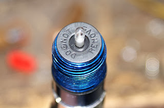
 Remove the plastic part labeled "DO NOT REMOVE". It just pulls right off.
 using a thin screw driver placed in one or both of the holes you see above. Push down or if needed lightly hammer the batteries out. DO NOT hammer directly on the plastic switch. The switch assembly will push all the way through the tube. Once you get the batteries out (if you get them out). You will need to clean out the tube. Use a small file, a hone, brass bottle brush, or whatever you can find that will work. Rinse out the tube and thoroughly dry it. Check that the silver tab is clean, then push the switch assembly back in place as you see it above. Replace the part marked "DO NOT REMOVE". Install the bulb and clean it off with alcohol. Reassemble the rest of the flashlight with new batteries.
 VOILA!

10/02/2013

Blonder Tongue FM only R-20

Got this off of the shopgoodwill auction site. It is FM only and the design is like a Granco 620U I have, but the speaker is WAY smaller and on the back of the radio.

Here it is, as I got it, quite dirty.
 
And after I recapped it, replaced the failing Selenium Rectifier with a silicon diode, and cleaned it up.
Here is the Schematic